|
|
|
The Luxeon Star LED and the Zetex ZXSC300
DC/DC Boost Converter Circuit
plus, conversion of the MiniMag 2AA Flashlight
This webpage was originally available at
http://www.5thcolumn.org but was removed for unknown
reasons. The page is now hosted by Daniel Towner. Copyright remains
with the original authors. Some HTML recoding has been performed by
Daniel Towner in order to reduce bandwidth requirements, and improve
consistency. All material in this webpage is used at your own risk and
neither Daniel Towner, nor any of the original authors provide any
guarantees as to correctness of the information given here.
It all started late October 2001 when Duggg on the Candle Power Forums posted this simple question:
http://www.zetex.com/3.0/pdf/ZXSC300.pdf. Although
the circuit is designed for the white Nichia NSPW500BS, I wonder if
it would drive an amber Luxeon Star with R1 set to 0.04 ohm, which
should pulse the LED at 475 mA.What resulted was three months of discussion and 30 some pages devoted to the topic regarding the possibility of using the Zetex ZXSC300 to drive the Luxeon Star LED with just two 1.5 volt battery cells. MrAl jumped in on the project and together with Duggg researched and analysed every aspect and component of the original circuit design as shown on the Zetex datasheets.
What they came up with was a very small sized, low parts count and highly efficient driver for the now popular Luxeon Star LED.
The finalized version of the Zetex ZXSC300 circuit produces the necessary >350mA current for the Luxeon Star at approximately 88% efficiency. The part count is low with only 5 components and the simplicity of the circuit lends itself to an easy and inexpensive solution to many flashlight modifications utilising the Luxeon Star LED's.
One of the goals in this project was to build the Zetex circuit and Luxeon into the smallest flashlight configuration possible. Duggg first succeeded in this endeavour by converting the very popular AA MiniMag flashlight. This webpage details that modification and provides other information regarding parts selection and printed circuit board designs.
Jump to the following sections within this page:
Several months of research and discussion on a public bulletin board have culminated in the successful development of a small converter module 14mm in diameter and 7mm in height that not only operates with 87% efficiency, but at a cost of less than seven dollars.
The recent introduction of the Luxeon Star high-power light emitting diode (LS) has sparked some interest in using it to replace the conventional incandescent and halogen bulbs currently found in most flashlights.
One such popular flashlight is the 2AA Mini Maglite (MiniMag), which has a head about 18mm in diameter and 23mm in length.
Since the MiniMag's bulb and reflector are almost the same size as the LS and its collimator, simply retrofitting the LS is relatively trivial. But, such a circuit is underpowered, since the LS has a typical forward voltage of 3.42 volts at its rated maximum current of 350mA---significantly higher than the 2.4 average volts provided by a pair of NiMH AA cells.
A DC/DC boost converter circuit could drive the LS at full power; the challenge then is to fit not only the LS and its collimator into the MiniMag, but to design a boost converter powerful enough to provide 350mA, and small enough to fit.
-Duggg-
For details, step-by-step instructions on how to perform the MiniMag conversion, see here.
 |
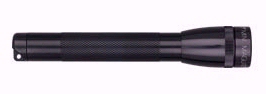
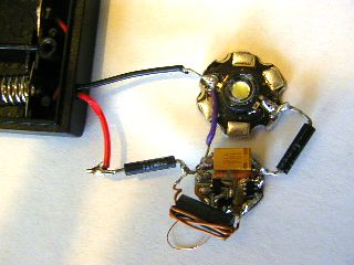
Here are the components. The Luxeon Star (LS) has the two wires attached. Below it is the transparent collimator. To the right of the LS is the inductor, a bead core wrapped with a few turns of magnet wire. |
 |
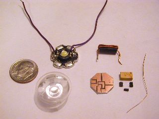
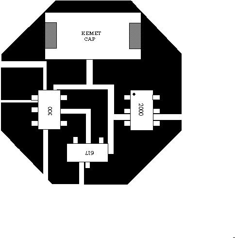
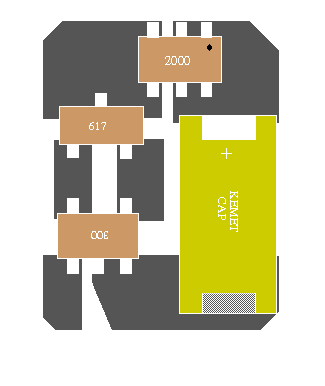
Below the inductor is the octagonal printed circuit board (PCB). To its right are the four SMD components, clockwise from top: the orange Kemet capacitor, the Zetex diode, the Zetex transistor, and the ZXSC300 chip. On the far right is a single strand of #32AWG wire which is the Rsense resistor. |
 |
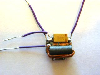
Calibration circuit. Black current sense resistor attached to the LS allows Rsense to be shortened until LS current is 380mA at 2.7 volts input. The current sense resistor in series with the battery allows the efficiency to be determined at 87.4%. |
 |
The Rsense resistor was then tucked behind the board, and the current sense resistors removed and replaced with leads. The vertical leads will go to the LS, and the horizontal leads will plug into the MiniMag's bulb socket. |
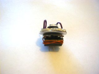 |
The PCB is inverted and the LS is connected. Below the inductor, unfortunately not very visible due to shadow, are the two power wires, trimmed very short |
 |
The PCB is carefully plugged into the socket and the collimator is gently placed over the LS to stabilize it as the MiniMag's lens holder is screwed on. |
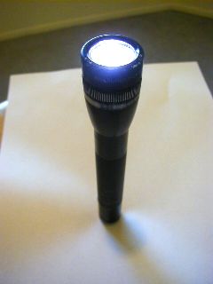 |
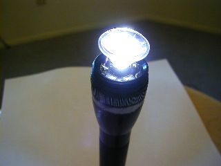
Here's the completed project. Note that no MiniMag was permanently harmed during this test! |
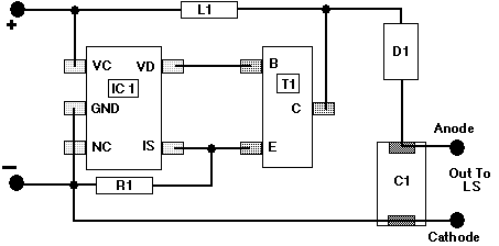
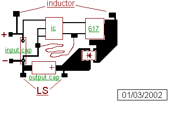
| IC1 | Zetex ZXSC300 |
| T1 | Zetex FMMT617CT |
| R1 | Resistor #32 wire |
| D1 | Zetex ZHCS2000 |
| C1 | 150uF Kemet Polymer Tantalum |
| L1 | Ferrite Bead Core - Hand Wound |
The Luxeon Star (LS) is a high-power light emitting diode. We used model number LXHL-MW1C, available from numerous sources including:
The LS comes mounted to an hexagonal heat sink, which needs to be filed or milled into a circular shape 17.5mm in diameter in order for it to fit inside the head of the MiniMag. Careful filing is necessary. If you don't file it enough, it won't fit. If you file it too much, it won't make good contact with the shell, and it won't be able to dissipate its heat.
Good heat dissipation is important in order to get maximum light output. It also helps lengthen the life of the LS. If you want to do a really good job, get a small tube of heatsink grease from Radio Shack, part number 276-1372 ($1.99) and line the edges of the LS and inside the MiniMag head where the LS sits.
An LS requires about 3.4 volts in order to draw its rated maximum current of 350mA. Since the project is only powered by two AA NiMH cells, which can provide only about 2.7 volts max, a DC/DC boost converter circuit is employed. The heart of our circuit is the Zetex ZXSC300 chip. At 3x3mm, it's small, yet with only 5 pins it's relatively easy to solder. It also requires a minimal number of support components, vital in order for everything to fit. The chip is available from Digi-Key, part number ZXSC300E5CT $1.05, or from Farnell InOne.
An inductor is simply a coil of wire. Just as a flywheel stores rotational energy, an inductor stores electrical kinetic energy. For our application, an inductor large enough to power the LS, but small enough to fit in the MiniMag, was needed. The size was reduced through use of a core, a cylindrical piece of material around which the wire is wound.
The actual core is a ferrite bead manufactured by JW Miller Magnetics, model number FB73-422. It's about 11mm in length and 5mm in outer diameter. We got ours from Digi-Key, part number M2308, $0.22.
Once the core is obtained, you need to find about 8cm of 24-gauge magnet wire. Check the Yellow Pages for electric motor repair shops. Many will gladly provide such a short length of scrap wire for free.
Run the wire through the bead's centre hole four times. It may be a tight fit. Then trim the ends to about 1cm, use sandpaper to remove the enamel insulation, and tin the exposed copper leads with solder.
The capacitor stores energy while the inductor is charging, and reduces ripple which could damage the LS. We needed a capacitor large enough to power an LS, but still small enough to fit inside the head of a MiniMag.
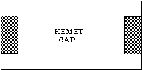
We chose a 150uF Kemet polymer tantalum, model number T520D157M010AS4350. It's available from Digi-Key, part number 399-1770-1, $3.75.
The diode prevents the capacitor from discharging while the inductor is charging. We needed one that could carry more than an ampere of peak current, yet have a very low voltage drop (as the higher the voltage drop, the less efficient the circuit is). We chose the Zetex ZHCS2000, available from Digi-Key, part number ZHCS2000CT, $1.29.
The ZXSC300 controls an external transistor, which does the work of charging the inductor. The transistor needs to handle in excess of an ampere of current, yet switch on and off fast enough to operate at nearly 400 kHz. We chose the Zetex FMMT617, available from Digi-Key, part number FMMT617CT, $0.99.
The circuit works by charging an inductor to a specified current, then discharging it. The chip monitors voltage across a resistor, and when that voltage reaches 19mV, the inductor is discharged. Because of that low voltage, a very low resistance is required, on the order of 12-18 milliohms.
Although SMD resistors can be found in such low values, they're often expensive. Moreover, the circuit requires some calibration to ensure that no more than 400mA is fed to the LS when the batteries are fresh, and since LS's tend to have widely varying forward voltages, an adjustable resistance is more desirable.
We found that a 32-gauge copper wire has a resistance of 5.5 milliohms per centimeter, so a 2-3cm strand is sufficient. The strand is carefully soldered to the edge of the board, then it is folded around to the back of the board and taped. This provides mechanical protection as well as electrical insulation.
You can often find 32-gauge wire in stranded lamp cord or speaker wire. In fact, 24-gauge stranded wire is often composed of seven 32-gauge strands.
A good flashlight provides a tight, intense beam. Spherical bulbs send light in all directions, and a reflector behind the bulb redirects this light forward. But since LEDs don't send any of their light backward, a reflector is not the right tool for the job. Instead, a transparent collimator is placed in front of the LED.
Unfortunately, at this writing, Luxeon does not sell collimators separately. They do, however, incorporate a small plastic collimator into their $15 LXHL-NW98 product (the "LS/O"). You can trim the 25x25mm square board down to the required 17.5mm circle. We just happened to have a spare collimator laying around, which we scavenged from an cyan LS/O we zapped a couple of months ago. It was thus more practical for us to order the smaller and less expensive LXHL-MW1C model.
We wanted a circuit board that would fit within the diameter of an AA cell, 14mm. The best design was an octagonal shape, which can be mass produced as squares, and then each corner can be quickly trimmed to produce a smaller diameter octagon.
The board has wide traces wherever possible, to minimize resistance and maximize efficiency. The wide traces also easily handle the peak current, which is in excess of one ampere. Spacing the components far apart makes soldering easier.
During the final stages of the Zetex 300 project I solicited
ideas for the smallest possible printed circuit board to be used
with the Zetex IC. Duggg, MrAl and myself summited design concepts
and produced the following information. From these concepts, I
finalized the three designs into actual printed circuit boards. In
the next section you can download images of these three boards and
from them, make your own boards or modify them to customize your
own design. -Mercator-
Here are a few PCB designs to consider. The finished diameter in all examples would be approx. 14mm. I have printed each design to actual size and placed the actual components on the traces. Each design shown here is feasible. The goal here is to come up with a usable design that will accomplish the following:
The photos shown on this page are not intended to be used "as-is" for the printing of the actual board. These examples are being posted to solicit your opinions, comments and ideas.
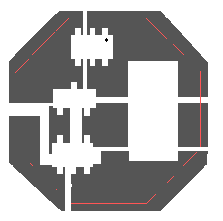
| Mercator's Original Octagon Design | |
 |
 |
Duggg's Original Hexagon Design | |
 |
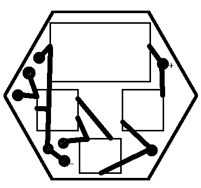 |
Duggg's design converted to Octagon: The octagon design provides a little more area to solder on leads. | |
| |
| MrAl's Component layout suggestions. This results in the smallest PCB design of the ones presented here. | |
 |
 |
You can use these images to create your own board designs. (scale is 1 to 10 - Millimeter to Centimeter).


The following three PCB designs can be downloaded and used to make your own etched boards. Each design, when printed to the specified size will produce a board suitable for many applications using the Zetex ZXSC300 IC and the listed supporting components. These three designs all have been printed, etched and tested prior to being offered here.
To use anyone of these designs you will need an simple image editing program that is capable of printing a image file exactly to certain specified dimensions. The graphics editor originally used to create and print these designs was Paint Shop Pro. Depending on the method of transferring the pattern to be etched you may need to make a mirror image and or a reversed image.
The files can be used to transfer the image to copper clad board with either the Toner Transfer Method or the UV Photo Sensitive Transfer Technique. For more information on making your own PCB's check this link: http://www.mnsi.net/~boucher/makepcbs.htm
Note: The original postings and/or web-pages contained large scale images of the PCB board designs. These are no longer available, and the images below will have to be scaled appropriately (Dan Towner)
| This design is the one featured in the MiniMag conversion preformed by Duggg. Each circuit board fits within a 14mm diameter. The Octagon design is easier to cut out than a circle. | 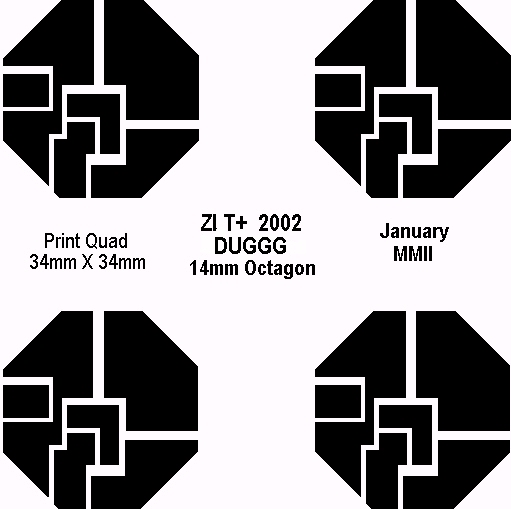 |
| This design is similar to Duggg's design. There is no small trace that runs under the Zetex 300 IC and there are larger areas to attach the input and output leads. Construction of this design is very similar to Duggg's board, Each circuit board fits within a 14mm diameter. The Octagon design is easier to cut out than a circle. | 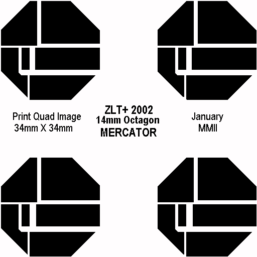 |
| This is the smallest design. Each circuit board measures only 0.425 inch by 0.450 inch | 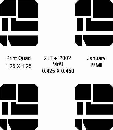 |
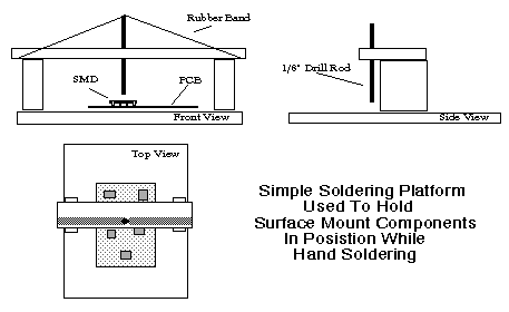
One of the problems in working with SMD's and using hand soldering techniques is to hold the part in position while soldering. In the past while replacing a bad component a very small dab of glue would do the trick. Working with a new board and soldering on the components with a conventional soldering iron, the glue trick isn't the ideal solution. I designed this platform using simple materials I had on hand. I used some scrap pieces of 3/8" ABS plastic sheeting, a short section of 1/8" drill rod (coat hanger), a rubber band and some ABS pipe cement. Assembly took less than a half hour. If you decide to build a jig like this take into consideration the size of the PCB you'll be working with and give yourself plenty of working room to easily get your iron into and to be able to see what you're doing. Several holes can be drilled on the top rail so that the pin can be positioned to either side. Tension on the part can be adjusted by either the length of the rod or the tension of the rubberbands. I secured a section of non-skid material under the PCB to keep it from sliding around. In actual use, all that you normally need to do is to solder one lead to the pad and then from there you don't need the jig any further for that one component.
-Mercator-
In this project the Current Sense Resistor and the windings of the Inductor are commonly available wire. These charts show the sizes and sources of this wire.
Table showing stranded wire sizes and number of strands of what size each strand is:
| #30 | 7 x #38 |
| #30 | 19 x #42 |
| #28 | 7 x #36 |
| #28 | 19 x #40 |
| #26 | 7 x #34 |
| #26 | 19 x #38 |
| #24 | 7 x #32 |
| #24 | 9 x #33 |
| #24 | 19 x #36 |
| #22 | 7 x #30 |
| #22 | 9 x #31 |
| #22 | 19 x #34 |
| #20 | 7 x #28 |
| #20 | 9 x #29 |
| #20 | 19 x #32 |
| #18 | 7 x #26 |
| #18 | 19 x #30 |
| #16 | 7 x #24 |
| #16 | 19 x #29 |
| #14 | 7 x #22 |
| #14 | 19 x #27 |
| #12 | 7 x #20 |
| #12 | 19 x #25 |
| #10 | 37 x #26 |
| #10 | 105 x #30 |
| #8 | 133 x #29 |
| #6 | 133 x #27 |
| #4 | 133 x #25 |
| #2 | 665 x #30 |
Chart showing American Wire Gage against bare wire dimensions
| AWG | INCH |
| 22 | 0.0253 |
| 23 | 0.0226 |
| 24 | 0.0201 |
| 25 | 0.0179 |
| 26 | 0.0159 |
| 27 | 0.0142 |
| 28 | 0.0126 |
| 29 | 0.0113 |
| 30 | 0.0100 |
| 31 | 0.0089 |
| 32 | 0.0080 |
| 33 | 0.0071 |
| 34 | 0.0063 |
| 35 | 0.0056 |
| 36 | 0.0050 |
If you intend to build the ZLT+ circuit is it highly recommended that you read and fully understand all the precautionary information, testing and construction techniques outlined on this page.
It is a good idea to either print out this page or copy it to you computer, so that you will have this valuable information readily at you disposal.
For the latest information regarding this circuit, please refer to the Candle Power Forums
The following information was compiled from various articles written by MrAl.
Hello, all....
In light of all the problems coming up with the Zetex 300 circuit (also known as the ZLT+) I thought a few words of caution were in order. Although most of this stuff can be found in the Zetex thread, actually locating it can be very hard.I found that doing a search took me to the beginning of the thread, which left me to manually search through some 400+ pages of info! Not something anyone wants to do.
So.....
I thought I'd condense all the precautionary tips and test procedures here onto one page.
First off, this circuit, as well as many other boost circuits, isn't your typical 'forgiving' circuit, in that if you do ANYTHING wrong, you wont be able to go back and correct it without buying more parts. This includes a whole host of problems such as reversed components, leads that break off during operation, battery voltage too high, etc., and especially incorrect components. Almost anything you can think of will blow some part or another in the circuit, or even worse: your new LS :-( I don't like this to happen to me, and I don't like this to happen to anyone else either, especially when i hear about losing $15 parts in quantities of two. The successful construction and operation of this circuit requires an almost perfect execution of construction techniques, plus a fairly high level of education regarding boost circuit pitfalls, plus the desire to run at least a few post circuit-construction tests. Given that all of the above are satisfied, you will find a very efficient circuit using the Zetex parts. I'll try to keep this short, but it's not going to be easy :-)
Also, see Summary below.
1) Component Selection
Since there has been quite a variance in store bought inductors, I can't recommend using ANY that come pre-wound on unknown core types. I have found that some store bought inductors saturate and don't come out of saturation, causing the output transistor to heat up and blow out (if the circuit is left on for more then maybe 10 seconds). The only kind of inductor that should be used here is a hand wound toroidal core type, as outlined in the Zetex thread. If you are using a store bought inductor, you may experience unusual problems with the output transistor heating up and blowing out. A decent test (although I can't say how conclusive a test this is) is to turn the circuit on and off about once every 5 to 10 seconds, while placing a finger on the copper clad next to the output transistor. If the clad stays cool while turning on and off at that slow frequency, the inductor is probably OK.If it starts to get very very warm or hot even ONCE, discard that inductor and look for a new one. This is very very important, because if the circuit is left on in that condition, the transistor overheats and is destroyed. It's not a good idea to hold your finger on the transistor itself, because with the kind of input sources typically used with these kind of circuits enough power can get to the transistor fast enough to cause immediate overheating or even an explosion, either of which would seriously burn your finger tip.
2) Construction
Every part has to be carefully soldered and a rough 'pull' test applied to each lead that hangs off the board. Firmly pull and twist each lead before turning on to make sure no leads will accidentally break off. Always remember: one, and only ONE tiny little mistake, will cost you a part. If you're lucky, it will be a cheap one, but more then likely an LS will fry. Inspect each connection with a 'eye loop' or similar magnifying lens to make sure there are no solder splashes or bad solder joints. It's soooo important to have everything PERFECT at the start. Check especially the clad trace runs between the transistor emitter and the chip input sense pin. This run should be tinned with solder while installing the chip and transistor. Also check the ground pin on the chip to make sure it is very well soldered. Keep the loop of wire used for the i sense resistor looped up above the board so that it can't touch any other parts.
3) LS Simulator + ripple detector circuit
Before you turn your finished circuit on for the first time and before you connect a real LS to the output of the circuit, you must perform at least one test. Connect the LS simulator and the ripple detect circuit to the output of the Zetex circuit and make sure you have an appropriate length of #32 wire connected for the i sense resistor (about 4 inches in length). Connect your dc digital voltmeter to the output also. Make sure the LS simulator gets connected correctly. The anode of the top diode goes to the positive output terminal. Connect a 2.4v source to the input of the circuit and look for some 2.5 to 3.5 volts on the output, while holding a finger on the transistor clad. Again, if the transistor gets hot, discard that inductor. Now turn off and connect the voltmeter across the 1 ohm resistor of the LS simulator. Turn on and look for 350mv across this resistor. Any less and you have to shorten the I sense wire to bring the reading up to 350ma. Turn off and shorten the wire by 1/4 inch, then turn back on and test again. Repeat until you reach 350mv, which corresponds to 350ma output. If you intend to use less then 350ma output, then you may reduce this to whatever value you want to use in the final application. Now turn off and connect the voltmeter to the output of the ripple detect network. Turn back on and take a reading on the meter. You should measure 50mvdc or less with 350ma output. Any higher means there may be a problem with the output cap. Make sure you are using the one described in the Zetex thread. Retest until you get 50mv dc or less. If you are setting up for less output current, such as 250ma, you can allow a higher output reading from the ripple network, but if you are using the right cap then you wont read more then 50mv anyway. A good idea also is to start out running your circuit at 250ma output, then after you have completed all the tests, pump it up to 350ma and repeat the tests.
4) Use GOOD, no wait... use PERFECT test practices
During tests, turn off your circuit before changing ANYTHING. It's so easy to turn off and then turn back on after the change is complete. In each case, when turning on hold your finger on the transistor clad to see if it gets hot.
5) Long term use
Coat the wire used for the sense resistor with something that will protect it from shorting to other parts. Double check all external leads for break strength. A broken battery lead can momentarily touch a parts' exposed lead, surely blowing something out. If you want to feel safer, use two parallel leads for the LS instead of just one for each terminal. That makes two leads for each LS terminal, two for the +ve terminal and two for the -ve terminal. Solder each of the two leads independently on the solder pads. If one lead breaks, the other lead will carry the current.
In closing
Keep in mind that the successful operation of this circuit is very possible. I've done over a hundred tests on my circuit and haven't blown out a single part of any kind. Of course, I followed the above guide lines to the letter :-)
I wish you all good luck with this and your other LED circuits! -MrAl-
Hello again everybody interested in the Zetex 300 circuit (or just driving the LS at 350ma average current), I found a pretty decent method of measuring the output ripple voltage. This means you can measure the approximate output ripple in order to determine if the output is suitably safe for driving the LS. Assuming you are driving it at 350ma, you wont want more then about 150mv of ripple voltage, because the dynamic impedance of the device is about 1 ohm around this voltage. This means for every increase in voltage of 0.15 volts there will be a corresponding increase in current through the device of about 0.15 amps. Since at 350ma the device can only tolerate another 150ma, we can allow only another 0.15 volts on top of whatever it happens to be running with 350ma average current through it. The only requirement is that you need a voltmeter with a 10 megohm input in order to measure this fairly important quantity. Since most digital meters have this feature, it shouldn't be hard to do. If you don't have a digital meter yet, maybe you should look into it. Even the cheap ones around 15 to 20 dollars (US) have 10 megohm inputs. Of course you want to check the specs before you buy, and while you are doing that make sure the dc scale measures down at least into the 100's of microvolts. This means you can measure a voltage such as 167.3mv on the 200mv scale. Beware some very very cheap meters wont let you do that; they will only read out 167mv on the 200mv scale, or else doesn't have a 200mv scale! That extra digit comes in handy for measuring voltages across small value resistors such as when measuring dc currents. OK here is the method, it requires a small network as shown below.
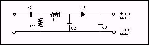
Connect as shown and set the meter on 2 volts dc. Fire up the circuit and read the dc volts on the meter. Anything over 0.050 volts is no good.Anything under 0.050 volts is good. Note that 0.050 volts dc out of the network is approximately equivalent to 0.100 volts peak ripple voltage which is about 0.1 amps ripple current through the LS. Thats the general idea, to have a go/no-go test for output ripple.
I tried various types of caps i had laying around. The results obtained reading the network output dc voltage correlated well with the actual ripple max output around 0.100 volts. I found that using high capacitance worked almost as well as low ESR capacitance. Using a low ESR tant cap 100uf, 20v, worked the best, but a combined total of 100uf and 300uf cheap electrolytics in parallel wasn't too bad either. Both came in under 0.050 volts dc with the network while the actual ripple was just under 0.100 volts for the electrolytics and under 0.030 volts with the low ESR cap, looking at the major harmonics. If you assemble your circuit and measure the output ripple to be over 0.100 volts (with the network) and you don't feel like adding another cap in parallel, you can also lower the average current somewhat if you change the current sense resistor or add a little resistance in series with it. If you read 0.120 volts for example, you can always lower the average current to 300ma and still drive the LS safely. The limit here though should be about 0.120 volts. Anything over 0.120 volts should be avoided in any case. Either get a better cap or add another one in parallel until it comes in under 0.120 volts. I would prefer a limit of 0.100 volts. With a limit of 0.100 volts you can be sure the circuit will run the LS safely. This means 50mv dc max out of the network.
Remember that the highest dc voltage allowable out of the Network is 0.050 volts dc (50mvdc), which corresponds to an actual ripple voltage of about 0.100 volts peak (100mv peak).
If you don't want to get a digital meter, you might be able to get away with using a JFET input op amp. They are very cheap too and have high input impedance. Set the gain for 1 and use the op amp as a buffer for the voltmeter. Since the output to the meter from the network is dc, it wont require a high speed op amp, just a general purpose JFET input like the LF353 or TL082.
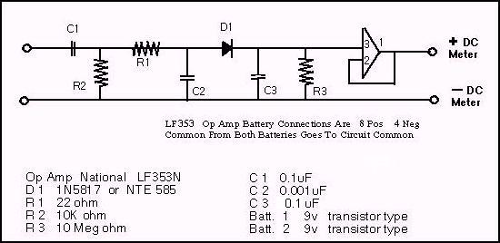
Since we have a dc output, we can connect an FET input op amp to the output of the network to use as a buffer without needing an amplifier that would have to respond to high frequencies. This would allow any kind of meter to be used.
Without the op amp, a digital meter should be used because of its high 10 megohm input. The op amp of course should have its own power supply, which could consist of two 9v alkaline batteries, one for the + supply, and another for the - supply. The op amp circuit could be made by simply connecting the inverting terminal of one op amp to it's output, and connecting the non-inverting input to "+ dc meter" and using the output of the op amp as the regular meter + dc input. This makes up a unity gain amplifier sometimes called a "voltage follower" connection. The type of op amp should be a JFET type, such as LF353 or similar.
| Note 1: | The LF353 power supply connections are: 8=positive, 4=negative, (there is no ground). |
| Note 2: | Power supply common is the common of the two 9v batteries. |
| Note 3: | R3= 10 megohm, 1/4 watt resistor. |
Good luck with it, MrAl
1) Can the Ripple Detect Network be connected in parallel to the LS simulator to measure the ripple and the output current at the same time?
Yes, it's made to check ripple either with the simulator or the real LS. You cannot connect both the real LS and the LS simulator at the same time though.
Can I use 1N4007 diodes instead the 1N4004 / 1N4006 in the LS simulator?
Yes, any diode in that series like 1N4001, 1N4002, etc. With this very simple circuit as a load, you have the freedom to experiment with various aspects of the circuit without worrying about blowing an LS.
Are there really only three diodes in series and not four (3 x 0.7 volts = 2.1 volts + voltage across the 1 ohm resistor or 4 x 0.7 volts = 2.8 volts + voltage across the 1 ohm resistor).
Yes, there are three diodes, not four. This doesn't mean you cant use 4 diodes, but when adjusting the current with the simulator before connecting the LS, it works out better to use the 3 instead. I get about 2.8vdc (measured) with three diodes and one 1 ohm resistor at about 350ma. My real LS's measure about 3.0 volts with 250ma, so if you want to use 4 diodes that will probably be OK, but keep in mind the current may go higher when you connect the real LS.
I have a better simulator on the drawing board which works almost the same as the LS to within about 2% or something between about 50ma to 500ma, but its not worthwhile to build because of the added complexity, and i haven't tested it in real life yet either :-) The simpler 3 diodes plus 1 ohm resistor simulator I used repeatedly over and over and had good results.
The only thing i noticed once was that one of the diodes had become disconnected in the series string, and had i not noticed that before turning on, it would have taken out the cap and maybe the transistor too. Always check all connections before turning on :-) On the other hand, if i had a zener or two connected across the output (as suggested by another CP forum postee) it wouldn't have mattered. I would have seen the higher output voltage and turned off.
Good luck,
MrAl
This page, written by Duggg, details the actual building of the Zetex ZLT+ LS Driver Circuit and steps needed to convert the MiniMag AA flashlight. The information provided here will be useful in building the circuit whether or not you plan on using the ZLT+ in a MiniMag Mod. Here you will find instructions on winding the inductor and adjusting the Rsense resistor. It is suggested that you either print out this page or copy it and view it off line with your Web Browser.
-Mercator-
Read All The Circuit Building Precautionary Info & Testing Techniques
Using diagonal cutters or tin snips, carefully trim the board down to its octagonal shape. Then lightly sandpaper the surface to remove any corrosion.
The easiest way to solder an SMD component is to melt a little solder on a trace first, then slide one pin of the component into the blob. For the "duggg" board, it is recommended that you solder the components in the order listed.
ZXSC300.Solder the side with the two pins first.
FMMT617.Solder the side with the one pin first.
ZHCS2000. Notice it has three pairs of pins. One end of the chip has a dot signifying the cathode pair; the middle pair are also cathodes; and the opposite end is the anode pair. It is important that the chip be placed so that the four cathodes are over one trace, and the two anodes are over the other. Only one cathode pin and one anode pin actually needs to be soldered, but you are welcome to do the others if you want.
Kemet capacitor. There is a red band on the positive end, and it's important that that end be connected to the trace leading to the diode.
Rsense resistor. Take a 5cm strand of #32AWG bare copper wire and carefully solder both ends to the board, as close as possible to the edge of the board. The strand will be shortened to the proper length in a later step.
Inductor. Take a 15cm length of #24AWG enamel-coated magnet wire. Using sandpaper, scrape 5-10mm of the enamel off one end. Heat the wire and coat it with a thin coat of solder (this is called "tinning"). Insert the tinned end of the wire into one end of the core, so that it sticks about 1cm out the other end. Now, take the other end of the wire, and stick it in the opposite end, and gently pull it through until it forms a tight loop, making sure the tinned end of the wire is still 1cm exposed. Don't pull too hard---the core is made of ceramic material which may break if subjected to stress.
Repeat the process two more times, until there are three adjacent loops on the outside of the core, and four wires in the middle. Notice there is barely enough room for four wires; be gentle when pulling the fourth through. Trim the non-tinned end to about 1cm, use sandpaper to remove 5mm of enamel, then tin that end.
To minimize circuit height, the inductor should be soldered to the top side of the board, aligned parallel to the capacitor and situated directly over the Zetex components. The adjacent loops should be oriented parallel to the board and away from the capacitor.
Power Leads.Take two 5cm lengths of magnet wire, sandpaper both ends, and tin one end of each. Attach the tinned ends to the boards.
Luxeon Star. Carefully file or grind the hexagonal LS board into a 17.5mm diameter circle, making sure the emitter is well centered. Solder the cathode of the LS to the negative pad on the board. Take care not to touch the emitter with the soldering iron! The anode will be attached in one of the next steps.
Inserting optional current sense resistor. If you have a 0.01-0.1-ohm current sense resistor available, solder it between the LS anode and the board. Place a voltmeter across the current sense resistor and apply power. Use Ohm's Law to calculate the current through the resistor by dividing the voltage by the resistance. For example, if you have a 0.1-ohm resistor and you show 25mV, then there is 250mA flowing through the resistor (and thus the LS).
Inserting milliammeter. If you don't have a current sense resistor, you will have to use a milliammeter to measure the current. Solder a 15cm length of wire between the LS anode and the board, then cut this wire in half and strip several centimeters off each end. Securely wrap the ends around the leads of the milliammeter. It is imperative that these be as solid possible. A loose connection may damage either the capacitor or the LS.
MiniMag preparation. Unscrew the head's end cap and set aside the transparent lens and the O-ring. Carefully remove the reflector. Unscrew the rest of the head, exposing the bulb. Remove the bulb. Insert freshly charged or new batteries. Carefully pry up the plastic part that the bulb plugs into (it is marked "Do Not Remove"). Observe the exposed sockets. The socket that connects to the case of the MiniMag is the negative.
Rsense adjustment. Make sure the Rsense strand isn't in contact with any components or metal surfaces. Apply power by inserting the appropriate power lead into the appropriate socket. The LS should light, and initial current should be well under 300mA. Carefully unsolder one end of the strand, and the LS should dim sharply to indicate the circuit is actually working correctly. Trim 3-5mm off the strand, and touch the trimmed end to the board. The LS should glow brightly again, and its current should be higher. Repeat this process a few times until current is 350-400mA with fresh batteries. Then solder the end near the edge of the board, so that it can be neatly folded around to the back side of the board.
Luxeon attachment. Disconnect power. Unsolder the current sense resistor or the milliammeter leads from both the LS and the board. Turn the board upside down. Cut a piece of paper the same size of the board and place it over the Rsense resistor, which should be in a circular or oval loop. Place the heat sink of the LS over the paper, then attach two short insulated leads between the LS and the board, sandwiching the Rsense wire and paper between them.
Board insertion. Trim the power leads very short and arrange them so that they can plug straight into the MiniMag bulb socket. Ideally, only 1-2mm of the ends should be exposed, to avoid possible short circuiting during insertion. Screw the MiniMag head on all the way, and liberally smear some heat sink grease on the inner diameter. Carefully insert the driver module, oriented so that the power pins will plug into the correct sockets. The LS should light. Now, carefully unscrew the MiniMag head just until it starts to come in contact with the LS. With the LS pointing straight up, set the collimator on top of the emitter, then screw the head end cap on until it just comes in contact with the collimator.
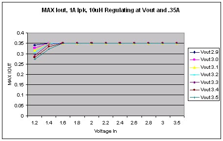
I'll be posting graphs and details of how the Zetex works. For now the equation I came up with to Compute Iout.
Iout Formula is MAXiout = Ilim - (1/2 * ( Vout + Vdiode
-Vin)/L)*dt) * (Vin/(Vout + Vdiode))
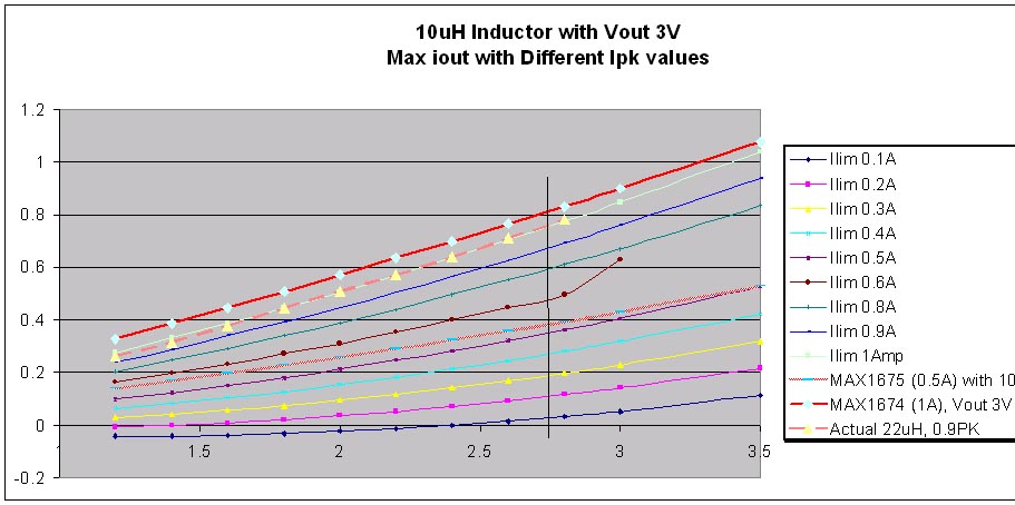
There are many plots here. At first this may be confusing. Of special interest is the upper light blue line with the second dashed red line over it. The light blue line was the computed Iout using the above equation with a 3V output setting and the dashed line are measured values of my test LS that runs around 3V. The two lines are almost identical.
Setting the Isense resistor moves you to a different line. Each line will show what the output current will be at different Voltages in. For a 2 AA battery design, One should only be interested in the 80% battery life which is 2V and higher.
The top red line and middle red line are the MAXIM ICs running MAXIout graphed for comparison reasons. For detailed information see the associated sections below.
The data I took for the real data is:
| Actual measured results with 33uH CoilCraft (0.090 ohms) DT3318 Inductor and 0.9A PK limit | ||||||
| Vin | Iin | Vout | Iout | Eff | Period | |
| 1.2 | 0.261 | #DIV/0! | ||||
| 1.4 | 0.316 | #DIV/0! | ||||
| 1.6 | 0.962 | 3.176 | 0.378 | 78.00% | 3.9us | |
| 1.8 | 0.999 | 3.186 | 0.446 | 79.02% | 3.4us | |
|
2 |
1.027 |
|
3.246 |
0.508 |
80.28% |
|
|
2.2 |
1.057 |
|
3.27 |
0.57 |
80.15% |
|
|
2.4 |
1.082 |
3.31 |
0.637 |
81.19% |
||
|
2.6 |
1.116 |
3.186 |
3.34 |
0.711 |
81.84% |
2.35uS |
|
2.8 |
1.143 |
|
3.38 |
0.78 |
82.38% |
2.2uS |
|
3 |
|
|
|
|
|
|
|
3.5 |
|
|
|
|
|
|
How did I know Ipeak was 0.9A? I'm using a Tektronix current probe which has a bandwidth of DC - 50MHz and I clamp it on the one of the wires to the inductor.
How did I get long wires on the inductor? I soldered two 22G wire ~ 2 1/2 inches long to the board where the inductor should go. At the ends of the wires I solder the inductor to be tested and the 2 1/2 inch 22G wire allows me to clamp on the Tektronix current probe.
A few scope pictures of the Zetex IC in action:
(Dan Towner) - Originally some of these scope shots were hyperlinks to other images - presumably larger images of the ones shown here. The links no longer exist however.
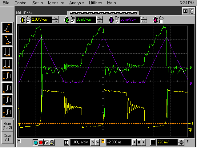 |
This actually doesn't look like a shot from the Zetex. Looks like the MAXIM IC waveforms since LX current is going to zero and it's longer than 2uS. Hmmm, how'd this picture get here. |
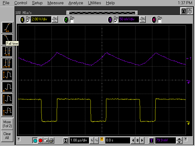 |
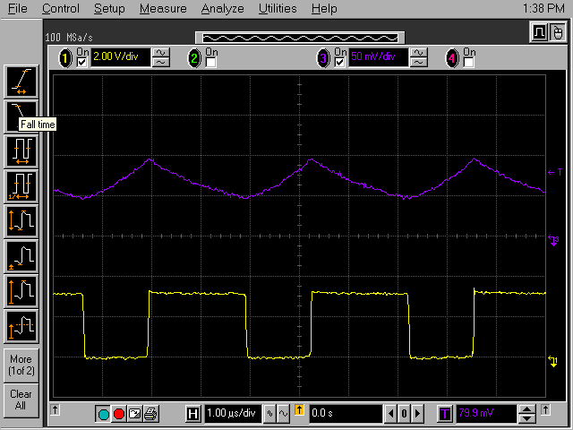
The purple trace it the Inductor current waveform. The yellow (bottom) trace is the voltage at the inductor SW node. (note: The high time is 2uS per the data sheet). |
 |
In this way I lose a little efficiency by adding some wire resistance, but I get inductor current waveforms and it is easier to change the inductor to a different value or size. I also have the LS with wires and a 2 pin connector. The board has 22G wires and at the ends are stripped back 1" or so. There is some additional loss in the wire and connector I measured 4-5mV drop on each leg. So, there is another fraction of a % loss. My setup will never give the best optimum efficiency numbers, but if I use the same setup for all DC/DC converters than this is a fair way to compare them since they all have similar losses. If one is 5% better, it's 5% better.So, in this setup my MAX778 measures about 65% efficiency at 0.3A.
This additional wire doesn't affect the performance of the regulator since the waveform and switching speeds on the inductor are typically not that fast.
Efficiency on the Zetex are controlled by many variables. I'm still looking at all the losses and trying to formulate an equation. Right now it's too complex. I can say, that the ferrite bead that the ZLT+ design uses is quite good and I've used it on the MAXIM ICs as well. With 4 turns on it the inductor is pretty good to around .6A - 0.8A. Above that it starts into saturation and having my ZLT+ set to 0.9 I was able to get it to go into smoke mode. Increasing Vin past 2.8 The LED jumped in brightness, the power supply current jumped and of course I jumped!
But, for those who just can't get enough overdrive, this IC can deliver the juice and will good efficiency. It would be almost impossible to build a discrete version of any form and get this kind of efficiency in such a small package.
The component count is probably by far the simplest design to date.
|
|
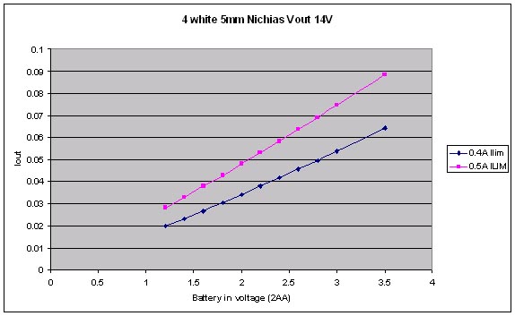
Setting Ilim to 400mA would drive the 4 white LEDs with about 50mA with a fully charged 2AA battery set and drop down to about 20mA output with nearly depleted batteries at 1.2V. The FMMT617 and output schottky diode limit how high the output voltage can go. The FMMT617 has a typical voltage rating of 18 Volts. Efficiency? One would have to wire one up and try it out. The graph shows Iout using the ferrite bead measuring in around 80uH with 4 turns. |
The Zetex data sheet showed the design driving one white LED, but, if it can drive one LS, then it should be able to drive several if not many white Nichia LEDs and do it efficiently. In fact setting Ilim to 0.5A or less the Zetex circuit is super efficient.
|
|
|
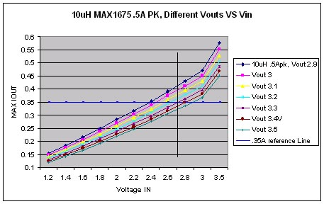
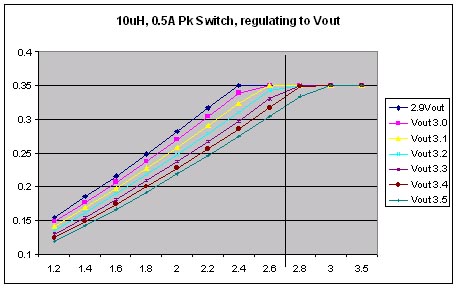
The MAXIM 1675 with a fixed setting of 0.5Amp peak switch current limit has a self limiting feature built in. It can't overdrive a regular LS if it wanted to. The vertical line in the first graph approximates the typical maximum voltage two AA NiMH, NiCD batteries fully charge are. So, choosing a low voltage LS that is 2.9 volts at .35 would be overdriven to a little over 400mA if the IC was running full throttle. Setting the feedback network to adjust the LS to regulate Vout to give us .35 Amps shows the regulator will regulate for a small range and then have diminishing current with lower input voltages. This slope is very similar to the Zetex IC but not exactly.
The above graphs are derived from the equation found in the data sheet on page 10.
I've taken data for one setting it it follows the graph exactly.
Efficiency: at fully charged batteries 2.2 - 2.6V 94-95% efficient.
Efficiency drops down to around 84% around 1.2 Volts and maintains > 75% down to 0.7 Volts.
|
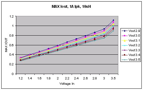
Setting Vout to 5V mode and hooking up a Luxeon Star to the output which clamps Vout to 3V and the MAXIM IC runs full throttle giving max Iout over the complete input voltage range. |
Setting the feedback resistor network to set the output to the LS voltage to give 0.35A of current and the MAXIM 1674 has enough to regulate constant voltage and current down to around 1.4Volts. Impressive. |
I've plotted different Vout since the LS can vary according to specifications from 2.9 to 3.5 Volts. Most units I've seen or others have reported to me have a voltage drop of 2.9-3.2 Volts. The lower the output voltage the more the MAXIM can deliver current for a longer time. See the 2.9Vout curve in the 2nd table above. It regulates down to almost 1.2 Volts before tailoring off. Of course Pout = Pin * eff. So, the input current is at least .875 + 10% or more. 2 AA batteries at this point are pretty dead and wouldn't hold regulation anyway. Below 2V the regulator eats the batteries up alive.
The above graphs are derived from the equation found in the data sheet on page 10.
I've taken data for one setting it it follows the graph exactly.
Efficiency: at the Vin 2.2=2.8 range is 89% and slowly tapers off to around 78% down around 1.2 Volts.